

CARA 1.0 (07/11/2025)
Introduction
CARA (Capstans Are Really Awesome) is my latest quadrupedal robot, following ZEUS, ARES, and TOPS. Built over the course of a year, CARA is easily my most dynamic and well-designed quadruped yet. Unlike most quadrupeds, CARA doesn’t use any gears or pulleys. Instead, her joints are driven by rope through capstan drives. CARA is also the second quadruped ever to use capstan drives, following Stanley. If you’re unfamiliar with how capstan drives work, I’ve made a 20-minute video — High Precision Speed Reducer Using Rope — that explains everything you need to know. CARA builds directly on what I covered in that video. Capstan drives offer several advantages: zero backlash, high torque transparency, low inertia, low cost, and quiet operation. These qualities make them an ideal speed reducer for robotics.
Finding the Exact 8:1 Gear Ratio
The starting point of this project was figuring out how to achieve an exact 8:1 gear ratio with the capstan drives. In my capstan drive video, I designed all the drives to have an 8:1 gear ratio—but when measured, none of them actually did. The commenters on that video pretty accurately diagnosed my mistake. I had made the outer diameter of the big drum 8 times larger than the outer diameter of the small drum, but this doesn't account for the diameter of the rope. It's the same kind of oversight that led to The SAT Question Everyone Got Wrong in 1982. Instead of using the outer diameters, I should have used the effective diameters—the diameters that touch the centerline of the rope wrapped around the drums. The effective diameter of a drum is the same as the pitch diameter of a gear.
In theory, using the effective diameters should result in a perfect 8:1 gear ratio—but in practice, it's a bit more complicated. Since the rope is thin and flexible, measuring its exact diameter is tricky. It gets even harder when the rope is wrapped around the drum and put under tension, which slightly compresses it and reduces its diameter. While approximating the rope’s diameter can get you close to an 8:1 ratio, achieving true accuracy requires a numerical approach of calculation. First, I used the estimated rope diameter to build two capstan drives: one with a gear ratio slightly below 8:1 and one slightly above it. The measured gear ratios were 7.912:1 and 8.213:1, respectively. The only thing I changed between the two drives, to achieve the different gear ratios, was the outer diameters of the big drums. With the two known ratios and their corresponding outer drum diameters, I used linear interpolation to calculate the outer drum diameter that would produce an exact 8:1 ratio. I then built a third capstan drive using the interpolated value. The measured gear ratio on that drive was 8.000619:1, which confirmed the accuracy of the method. The CAD files for the 8:1 capstan drive test stand are available on my Patreon Shop and through my Patreon Builder Tier.
In theory, knowing the big drum diameter for the exact 8:1 drive should allow me to back-calculate the rope’s precise diameter, which I could then use to design other capstan drives with exact gear ratios. I have yet to confirm that this works.

Outer diameters of the drums

Effective diameters of the drums
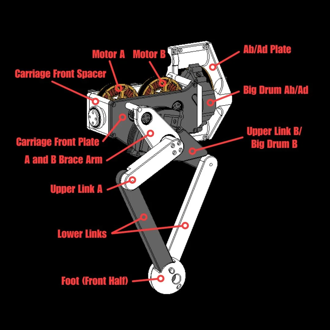
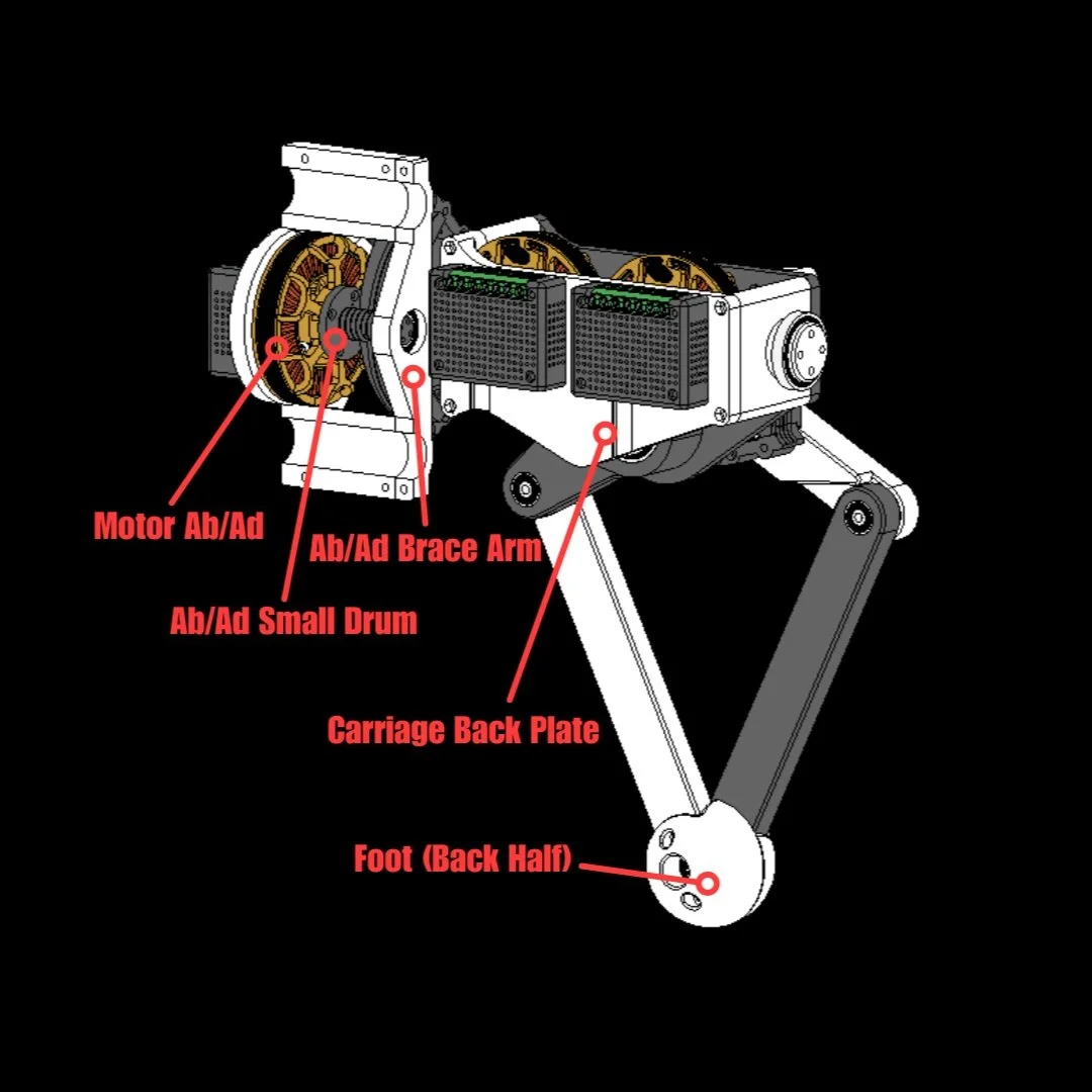
Leg Design
CARA’s leg design is her most essential subassembly, so I spent more time designing a single leg than any other part of the robot. In the capstan drive video, I tested two different quadrupedal leg designs: a coaxial 5-bar linkage and a standard quadruped leg. I chose the 5-bar linkage for a few reasons. First, it distributes loads more evenly between its motors. Second, it's significantly more compact. And third, 5-bar linkage legs are heavily underutilized in quadrupeds. So, for the sake of uniqueness, I felt it was the best choice for CARA.
The leg has three joints: a, b, and ab/ad. Joints a and b belong to the 5-bar linkage, while the ab/ad joint rotates the entire linkage. Each joint is powered by an 8:1 capstan drive using 2 mm Dyneema DM20 Rope, which has essentially zero creep. Each capstan drive is driven by an Eaglepower 90KV BLDC Motor. These pancake-shaped motors have large gap radiuses, which give them high torque—ideal for Quasi-Direct Drive (QDD). Motor control is handled by ODrive S1 FOC Controllers. Since these boards have onboard magnetic encoders, they were mounted below the motor shafts. I attached 8 mm Encoder Magnets to the motor shafts using custom 3D-printed couplers. I also designed custom 3D-printed ODrive covers with perforations for passive cooling.
The robot’s feet are made of two identical TPU 95A half-spheres, screwed onto the lower links of the 5-bar linkage. All small drums were printed in PET-CF, while the rest of the structural parts were printed in Polycarbonate (PC). I chose PET-CF for the small drums because they experience the highest stress and PET-CF has higher strength compared to PC. In retrospect, it might have been better to print everything in PET-CF—it doesn’t suffer from warping and would have only cost around $4 more. The downside is its significantly longer print times. The feet and small drums were printed at 100% infill, while all other parts used 25% gyroid infill. The gyroid pattern offers isotropic strength, an excellent strength-to-weight ratio, and fast print speeds.

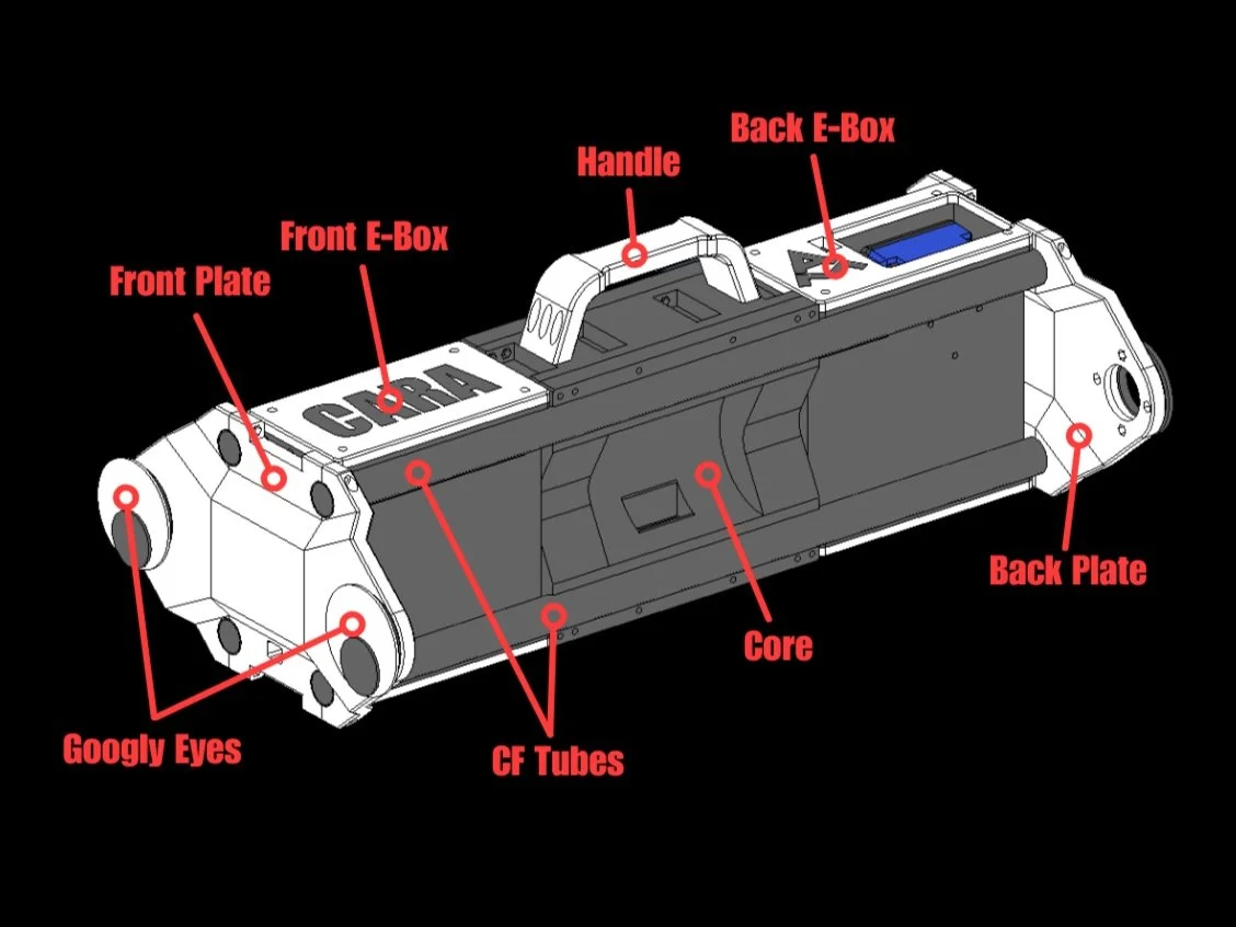
Robot Design
The robot’s design is relatively simple, considering the legs make up most of it. All four legs mount to the core of the robot and also clamp four carbon fiber tubes in place. These tubes run the full length of the robot and form its structural frame. Carbon fiber was chosen for its high strength-to-weight ratio. The front and back plates provide extra bracing for the legs. These plates also clamp onto the ends of the carbon fiber tubes to improve overall rigidity. Electronics boxes are located at the front and back of the robot to house electronic components and wiring. Like the feet, the robot’s handle was printed in TPU 95A.
The brain of the robot is a Teensy 4.1 Microcontroller. All CANH and CANL wires from the ODrives connect to a CAN Bus Transceiver, which then connects to the Teensy. CARA is controlled with an 8-Channel RC Transmitter and Receiver. For power, the robot runs on a 24V 3000mAh Kobalt Battery, which clips onto a Power Wheel Adapter and charges using a Compact 24V Kobalt Charger. Admittedly, 3000mAh is quite low for a robot of CARA’s size, but I already had two of these batteries from a previous project (Impulse). To save money, I chose not to buy a new battery. A 40A fuse was used to protect the electronics, and a Voltage Regulator set to 5V powers the Teensy from the main battery. For orientation feedback, CARA uses the BNO086 IMU.
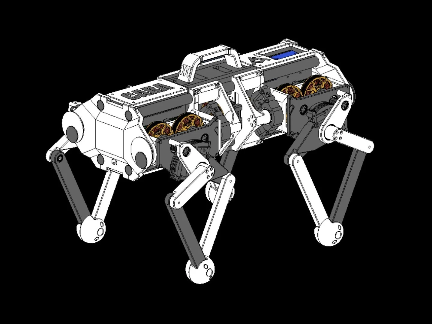
CARA weighs 31.41 lbs (14.25 kg) and measures 24.82 × 17.98 × 16.83 in (630.55 × 456.81 × 427.51 mm) . This is roughly the same weight and size as TOPS, my previous quadruped, which used the same motors and motor controllers. The total cost for CARA is approximately $3,300.
Programming
Homing
The first step in programming CARA was to create a homing sequence for the joints. This sequence works the same way as the one shown in the capstan drive video. Since there are only absolute encoders measuring the position of the motor shafts, the position of the joints can only be determined relatively. The homing sequence begins by spinning each joint to its physical limit, which is detected by a rise in current draw. Once this limit is reached, the absolute position of the joint can be established. This homing process must be run once at every startup.
Kinematics
I derived three sets of kinematic equations for CARA: inverse kinematics (IK), forward kinematics (FK), and rotation kinematics (RK). The IK equations determine the joint angles needed to place the foot/end-effector at a specific X, Y, Z position in space. The FK equations do the opposite—they calculate the foot’s X, Y, Z position given the current joint angles. Both sets of equations are used for trajectory planning. To move a foot to a specific location, the program first uses the FK equations to determine its current position. Then, knowing both the current and target positions, the code interpolates the waypoints in between. This allows the foot to follow a smooth, predictable path to its target position, rather than jumping there abruptly. I used the Arduino RAMP Library to interpolate these waypoint positions. The IK equations are then used to determine the joint angles at each waypoint. The RK equations are used to calculate the foot positions required to rotate the robot’s body—about its center—in the roll, pitch, and yaw axes. After determining the foot positions using RK, the IK equations are again used to compute the joint angles. RK is primarily used for pose control and stability. Pose control allows the robot to demonstrate its dynamics by rotating in place, while stability (discussed further below) ensures that the robot remains balanced.
Gait
To make CARA walk, I used a cycloidal step trajectory, which offers smooth takeoff and landing for the feet, along with a natural-looking gait. I also tested triangular and rectangular step trajectories, but they performed worse in terms of smoothness, leg clearance, and natural appearance. CARA’s gait follows a trotting sequence, where diagonal legs move at the same time. Each step is composed of two phases: the swing phase and the stance phase. The swing phase occurs when the foot moves forward through the air, while the stance phase occurs when the foot moves backward on the ground to propel the robot forward. The gait sequence alternates which pair of diagonal legs are in swing and stance phases, creating a continuous walking motion. Walking in any direction other than forward uses the same trotting pattern, except the legs step at an angle rather than straight ahead. Turning works a bit differently. While turning, one pair of diagonal legs steps outward while the other pair steps inward.

Stability
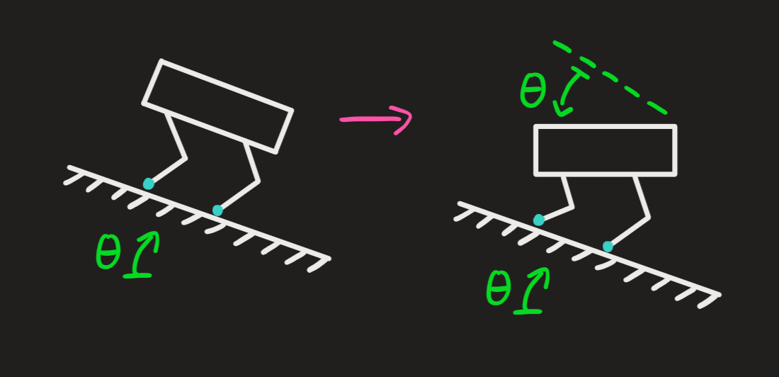
CARA is the first quadruped I’ve implemented stability control in. With stability, CARA is able to stay level on inclines and recover from external forces while walking. Implementing static stability (stability while standing still) is relatively simple. The robot continuously measures the incline angle of the surface using the IMU, then rotates its body—about its center—at an equal but opposite angle to stay level.
Dynamic stability (stability while walking) follows roughly the same approach, but with a key difference: the robot does not continuously read the IMU to adjust its orientation. Instead, it only checks the IMU to update its orientation when all four feet are on the ground, which happens once per step cycle. This ensures that orientation changes occur when the robot is in its most stable configuration. I also found that updating the robot’s orientation too frequently during the stepping sequence leads to instability, as the robot never settles into a steady state.
Moving Forward
Things to Fix
Overall, I’m happy with how CARA turned out. Her design is quite robust, and there’s not much I would change. Some parts did break on multiple legs during testing, but I redesigned them to be stronger. The two things I would consider changing in future iterations would be the battery and the foot material. As mentioned earlier, the current battery has a relatively low capacity. I’d like to switch to a battery with at least double the capacity and even more voltage. This would require slight design changes, since the current battery fits perfectly in the electronics box. Regarding CARA’s feet, I want to move to a more durable material than TPU. During outdoor testing, I noticed that CARA’s feet wore down quickly when walking on concrete. I believe silicone would be a better option for long-term durability. On the software side, the main thing I’d like to improve is the gait sequencing. Right now, CARA doesn’t lift her legs high enough to step over obstacles because it causes instability. Fixing this—possibly through reinforcement learning—would be an interesting follow-up project.
Things to Add
There are several things that I would like to add to CARA’s hardware and software in the future. On the hardware side, I think it would be interesting to give CARA wheels, similar to the Unitree B2-W. I also intentionally designed the top of CARA with mounting points for future attachments. One of these is a GoPro mount, which I used in the video. I’d like to create and/or retrofit more unique attachments, such as a Nerf gun, a LiDAR sensor, or even a robotic hand. On the software side, I’d like to give CARA more autonomous capabilities. Object detection would be a great starting point.
The next robot dog I build will most likely be a smaller, more builder-friendly version of CARA, complete with a step-by-step build guide. That project will probably happen sometime in 2026.