
Infinite Spinning Top (01/16/2026)
Introduction
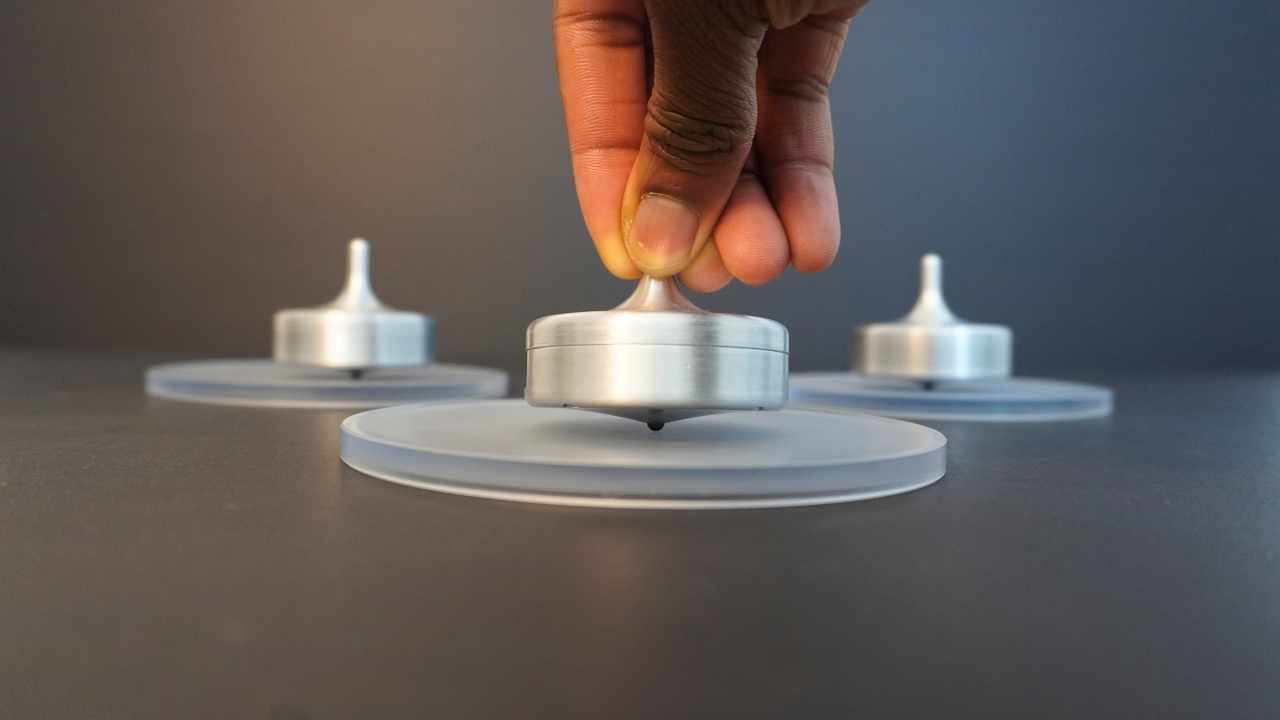
Spinning tops are such fascinating mechanical toys. Using the concepts of angular momentum and gyroscopic precession, they balance on a single point, seemingly defying gravity itself. Still, most traditional spinning tops only spin for a good 30 to 60 seconds. I wanted to see how far that limit could be pushed, so I built a spinning top designed to spin for hours. Is this true perpetual motion, or just clever engineering? Spoiler alert: there’s a hidden battery.
If you’re interested in building your own infinite spinning top, you can purchase the full build guide on my Patreon Shop or access it through my Patreon Builder tier membership.
Generating Spin
Going into this project, my one rule was that everything that generates spin in the spinning top must be located within the shell of the top. This best preserved the idea of what a spinning top is: self-contained. This rules out those “perpetual motion" machines that you might see with an electromagnet inside the platform. This also rules out any electric spinning top that has a motor that directly spins the top on a surface. Ruling these ideas out, my mind immediately turned to reaction wheels as they seemed to be the most obvious way to generate spin in a body. Reaction wheels are devices used to rotate or stabilize a system. They’re most commonly used in satellites to allow them to orient themselves in the vacuum of space. The two main ingredients of a reaction wheel are a motor and a weighted wheel. Reaction wheels work under the principle of conservation of angular momentum. Since the total angular momentum of the system must be conserved, when the motor accelerates and therefore applies a torque to the weighted wheel, the weighted wheel must then also apply an equal and opposite torque back onto the motor. This causes the base of the motor to accelerate in the opposite direction. Another way of looking at this is through the lens of Newton’s 3rd law. For every action there is an equal and opposite reaction.

While reaction wheels can generate spin in an object, they have one important caveat. They can’t generate spin continuously because motors can’t accelerate forever. When a reaction wheel motor reaches its top speed, this is known as saturation. The easy way to desaturate a reaction wheel is to decelerate the motor, but in doing so, you essentially undo your previously generated spin. One way I thought about getting around this was to mount the motor on a one-way bearing to allow it to desaturate without undoing the previously generated spin, but this method would require periodic accelerating and decelerating phases, which would be super choppy and inefficient.
To solve the issue, I turned to eccentric rotating masses (ERMs). These are essentially motors that spin an off-center weight, generating a ton of vibrations. This is the same technology that creates the buzzing in your phone, the vibrations in electric toothbrushes, and the haptic feedback in game controllers. So how do vibrations help create circular motion in a spinning top? Well, imagine swishing a ball in a bowl. Let’s say that the ball is the tip of the spinning top and the bowl is the surface that the top spins on. By adding “vibrations” to the bowl by swishing it around, you generate circular motion in the ball. So by putting an ERM in a spinning, you can essentially generate spin through vibrations. Another way to think about this is that the off-center weight causes the top to lean in one direction, so when the weight spins, the top wants to lean in all directions super fast, which generates spin.
The Design
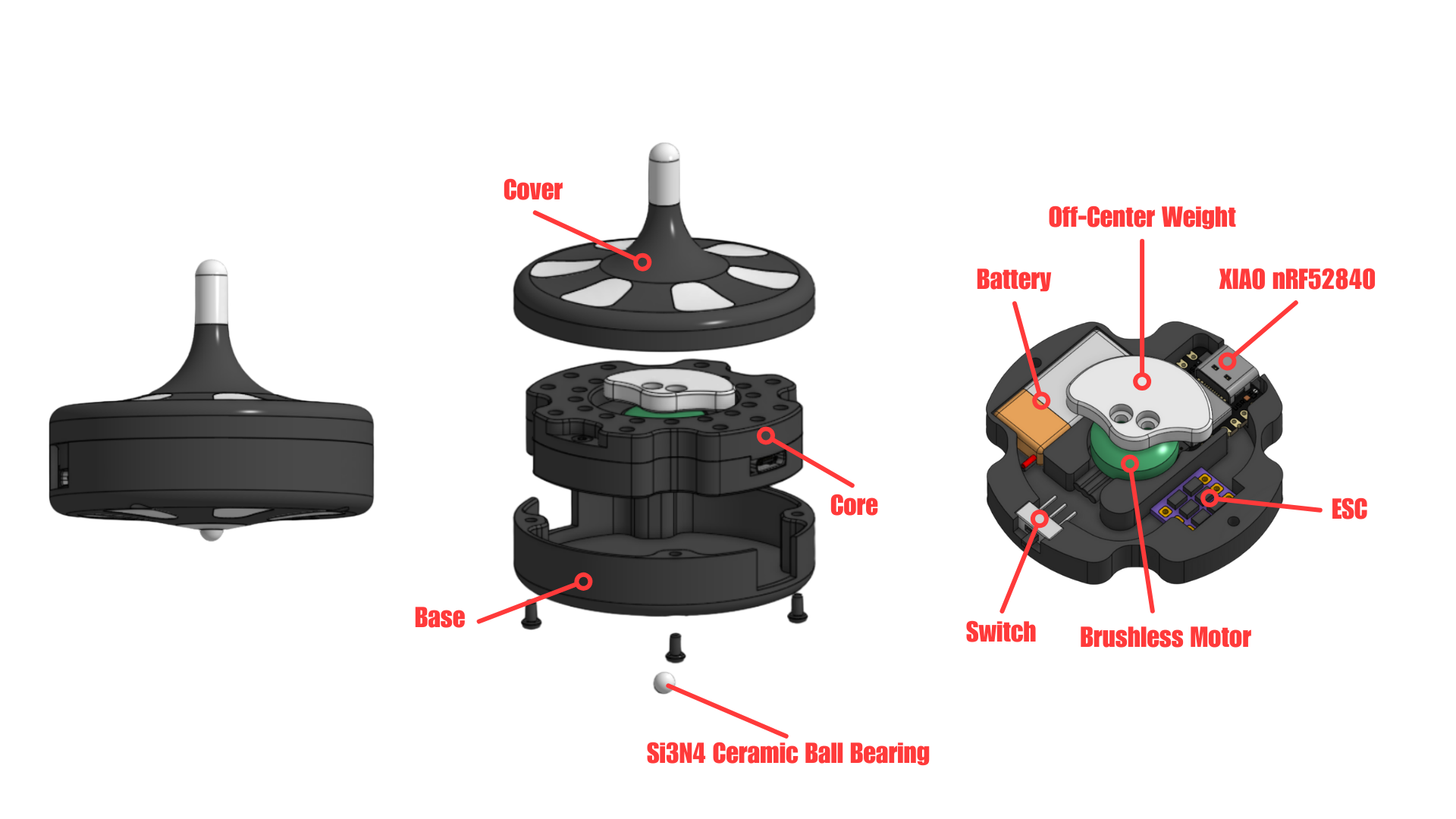
The design of the core of the spinning top features a 1202.5 11000KV Brushless Motor, an aluminum off-center weight, a 1s 150 mAh Li-Po battery, a XIAO nRF52840 microcontroller, a 1S 4A ESC, and a switch. These specific electronic hardware were chosen mainly d ue to their small size. The battery can be recharged through the XIAO since the XIAO has a built-in charger circuit. I originally designed the core to be as compact as possible, without much regard for how well it was balanced. To balance the core, I redesigned the top of the core to have holes for screws so that I could use the screws as counterweights. I used a technique called static balancing to pinpoint where to put the screws. This method required the core to be freely spinning, allowing the core’s heavy spots to drop to the bottom due to gravity. Then, the screw counterweight can be placed opposite to these heavy spots.
One thing I wanted to investigate in the project was the best control scheme to optimize the top’s power flow. I figured that spinning the ERM at a constant speed would waste energy at times when the top didn’t need to spin as fast. My mind instantly went to using a PID controller for this optimization problem. Using the speed of the top as the input, the controller would then be able to determine if the ERM needs to spin faster or slower to maintain a certain spinning top speed. The one issue here is that it’s difficult to get a high-speed spinning object to measure its own speed. My first thought was to use the XIAO’s onboard 6-axis IMU to measure the top’s speed. Unfortunately, the XIAO’s gyro sensor can only measure a max of 2000 dps (~333RPM). My next thought was to build a hall effect tachometer into the top. By adding a magnet to the off-center weight and a hall effect sensor to the top’s core, I could approximate the speed of the top by doing some very hacky relative velocity calculations. Unfortunately, this measurement method was a little too hacky and prevented me from getting any good speed readings. After this, I reverted to using the IMU, but using the accelerometer this time. Although they only measure linear acceleration, an accelerometer can be used to measure angular speed. This relies on a simple circular motion concept. The centripetal acceleration of an object is defined as ω^2*r where ω is angular speed, and r is the radius of the object’s rotation. This equation shows that you can calculate the angular speed of the top given its centripetal acceleration, which can be measured from the accelerometer. Unfortunately, accelerometer data is notoriously very noisy. There are also a lot of unaccounted-for forces that skew the accelerometer’s centripetal acceleration readings. In the end, I found that just commanding the ERM to spin at a constant speed worked perfectly fine, even if it meant using a bit more energy than needed at times.
Design Optimization
How do you design the optimal spinning top? This was a question that I had been asking myself since the beginning of the project, so I decided to investigate it. After prototyping many spinning tops, I settled on 3 key design parameters that determine the performance of a spinning top.
Moment of Inertia: The moment of inertia of an object is proportional to m*r^2, where m is the object’s mass and r is the object’s radius. By maximizing the top’s moment of inertia, you maximize its starting energy. In other words, heavy and wide spinning tops will generally spin longer. Now, when it comes to an electric spinning top, such as the one I built in this project, the moment of inertia of the top itself isn’t as important since the starting energy doesn’t necessarily dictate the top’s spin time. Instead, the moment of inertia of the off-center weight matters here. You want your weight to have a high moment of inertia so that it generates enough vibrations to keep the top spinning. This was a realization that I took too long to realize. I had originally used a 3D printed off-center weight and found that the top wouldn’t consistently spin for long periods of time. I then switched to an aluminum off-center weight and saw much more consistency.
Center of Mass Height: The height of the top’s center of mass determines the torque that gravity applies to the top to knock it off balance. A top with a shorter center of mass height will generally spin longer. Intuitively, this makes sense. Taller things are more susceptible to tipping.
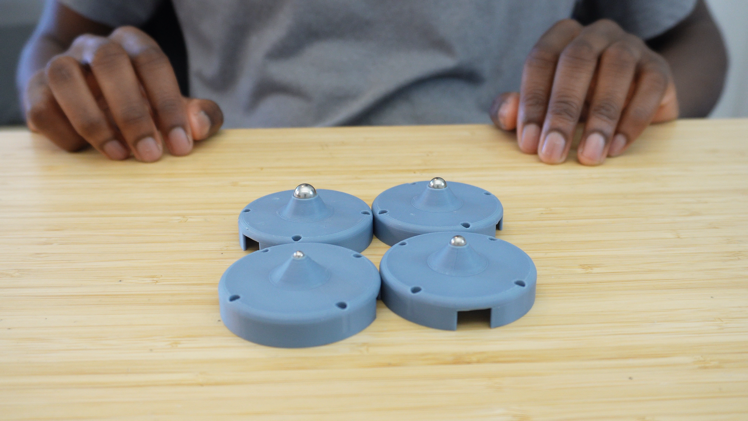
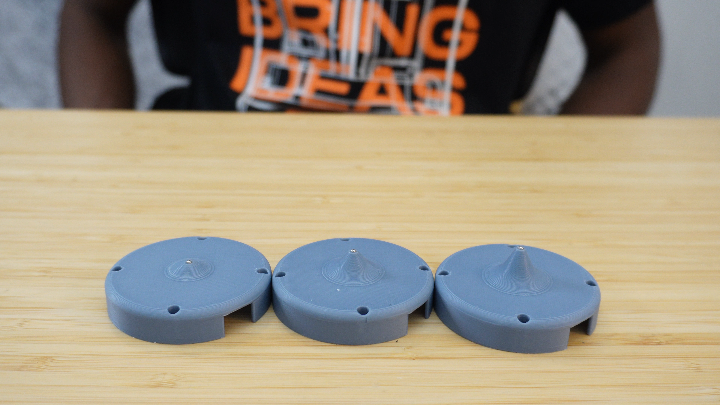
Tip Size: The size of the tip determines how much friction is applied to the top to slow it down. The smaller the tip, the smaller the contact area with the surface, and the longer the top can spin for. By this logic, a sharp point is the most effective spinning top tip. The one tradeoff here is that a sharp point can easily wear out, so it’s best to use a steel ball bearing. You can even use a silicone nitride ball bearing if you really want to optimize the tip. Silicone nitride ball bearings are harder and have less friction than steel ball bearings. For an electric spinning top, I actually found that a medium-sized tip worked best since it allowed the top to be more stable when precessing.
Results
In the end, I was able to consistently get around 90-120 minutes of spin time from the spinning tops on a fully charged battery. I was honestly hoping for a much longer spin time, but I think this is a good start. I definitely want to revisit this project in the future to see just how long I can get a spinning top to spin. Right now, the battery is the main limitation. In the future, using a high-capacity battery or using a motor that pulls less power could be beneficial in maximizing spin time. I also want to revisit the idea of optimizing the top’s power flow through controls because I think there’s potential there.