
Internal Cycloidal Actuator (02/14/2024)
About
Having designed many robotic actuators, one recurring challenge that I found is achieving compactness. Ideally, a robotic actuator should be as slim as possible, especially for legged robots. To fix this, I decided to try a new design approach. Instead of using an off-the-shelf BLDC motor for the actuator, I decided to design my own BLDC motor. This gave me the liberty to add the gearbox in the center of the motor thus making the actuator compact. In my opinion, this is the optimal actuator design as there are no performance tradeoffs. I first saw this design scheme implemented in the MIT Mini Cheetah robot which has a 6:1 internal planetary gear drive in the center of its actuators.
GitHub (For CAD and BOM)

Specs and Results
36N42P Configuration
⌀125 x 84mm
Total Mass: 1023g
Total Cost: $384
Speed: 209RPM @ 22.2V
Torque: 16.17Nm
Motor phase resistance: 75 mOhm
Motor phase inductance: 41.05 µH
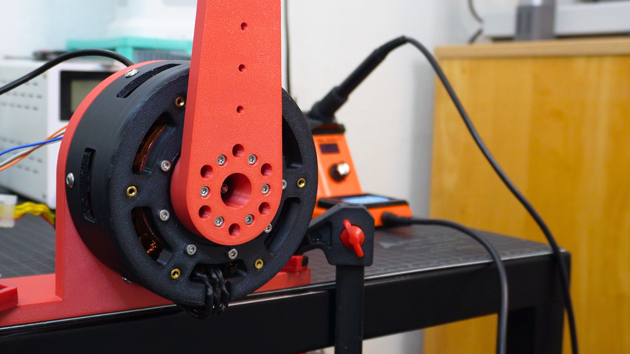
How it works
The actuator design utilizes the QDD (Quasi Direct Drive) scheme which means that it uses a low gear reduction to retain speed and efficiency. This also means that the motor needs to have high torque in order for the actuator to be powerful. I did this by designing an outrunner BLDC motor. Outrunner motors have high torque densities because of their large gap radiuses. I purchased a 10010 stator with 36 slots from Aliexpress. I coiled it myself using 6x strands of 26AWG copper wire doing 6 turns per slot. (effectively 36 turns per slot). The stator is made from laminated steel sheets which should increase the flux of the motor as well as prevent eddy current loss.
I designed the rotor of the motor and machined it out of mild steel 1045 using PCBWay. Making it out of steel should increase the flux of the permanent magnets attached to the rotor. I mounted 42x N52 grade magnets to the rotor using JB Weld. Interestingly JB Weld has 11% steel making it ferromagnetic. This should actually increase flux though not by a significant amount.
The actuator uses an 8:1 cycloidal gear drive which is located in the center of the motor. The Fixed ring of the gearbox (composed of roller pins) was machined out of aluminum 6061 and was fit into the center of the stator with Loctite 648 retaining compound. The eccentric shaft of the gearbox directly mounts to the rotor of the motor. The gearbox is essentially part of the motor. Designing the gearbox was the most challenging part of this project since it required the use of small bearings and spacers.
The actuator uses an ODrive S1 FOC Controller giving it the ability to lift loads and move to exact positions. Overall, this actuator worked quite well. The only issue that I ran into was with the 3D-printed parts slightly warping due to the heat from the coils. A fully metal gearbox is probably the best way to go next time.
