Ball Balancer (04/26/2023)
About
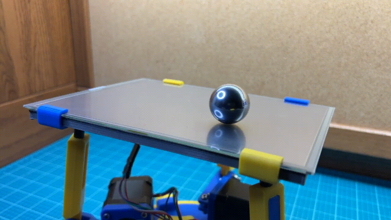
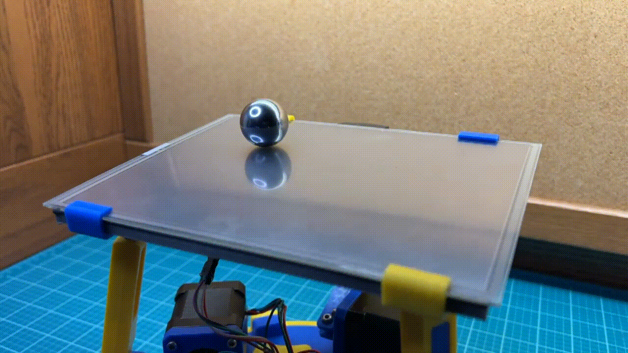
Several months prior to this project I created this ball balancer. It's able to balance a 1.5" 3D printed ball on an 8" x 8" platform. I decided to revisit this project to make an even better ball balancer. This iteration is quieter, less bulky, easier to build, and more precise. Not only can this version balance a ball but it can also move the ball around in different patterns.
Github (For CAD, Code, and BOM)
Inverse Kinematics
The machine is able to angle itself through the use of inverse kinematic equations. These equations calculate the position to move each stepper motor in order to achieve the desired platform orientation. I derived these equations myself mainly using vector calculus, trigonometry, and lots of patience. The equations are fully parameterized meaning that they would work with any 3RPS parallel manipulator of any shape or size.
Stepper Motor Control
Simply having a ball-balancing algorithm only got me so far with this project. During my initial testing, I found that I had very jittery motion. To solve this, I decided to make the speed and acceleration of each stepper motor proportional to the difference between the motor’s current and target positions. In other words, when a motor is close to its target position its speed and acceleration are low, and when it’s far away from its target position its speed and acceleration are high. In addition to this, I also decided to switch the drivers to 1/16th micro stepping which means that instead of having 200 steps/revolution they have 3200 steps/revolution which makes actuation much more smooth and more precise.
Patterns
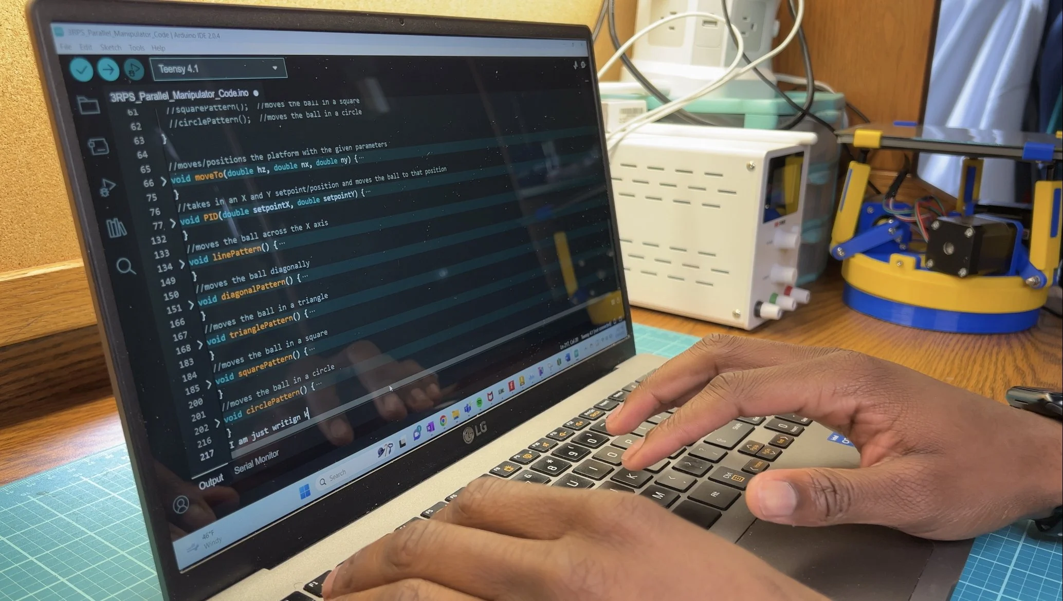
The balancer can also move the ball around in different patterns. Implementing this was fairly simple. The ball balancing algorithm moves the ball to the center of the platform. But if you change what the platform thinks is the center (ie change the setpoint) then you can move the ball to a different point on the platform. Constantly doing this creates motion and doing this with equations creates shapes. You can essentially create any shape that can be described in rectangular equations, parametric equations, or polar coordinates. Here are the shapes that I was able to create.
line
rectangle
triangle
circle
ellipse
sinusoidal functions
zigzags
figure 8
Design Approach
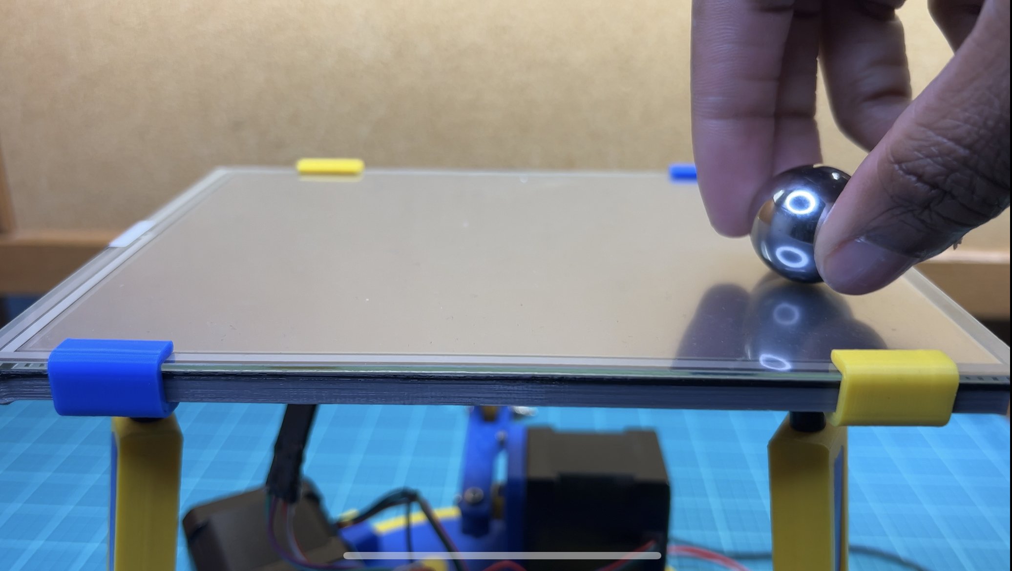
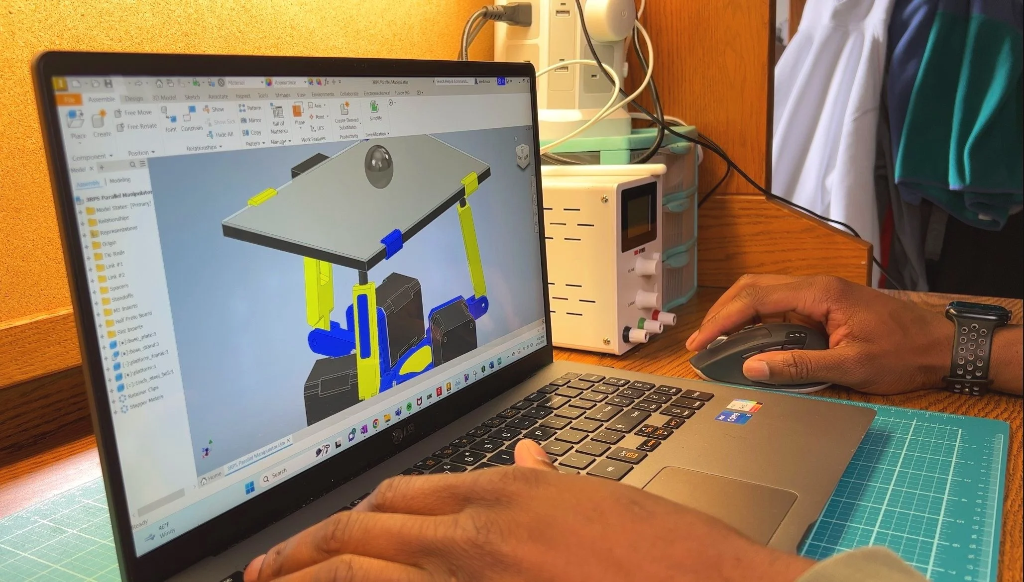
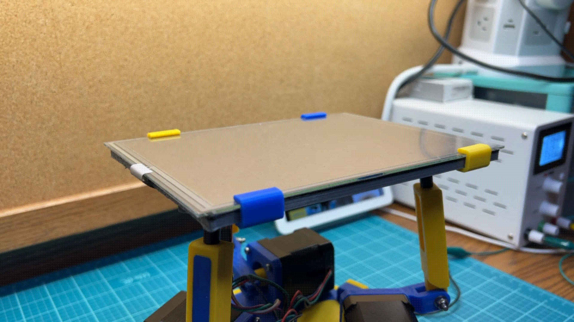
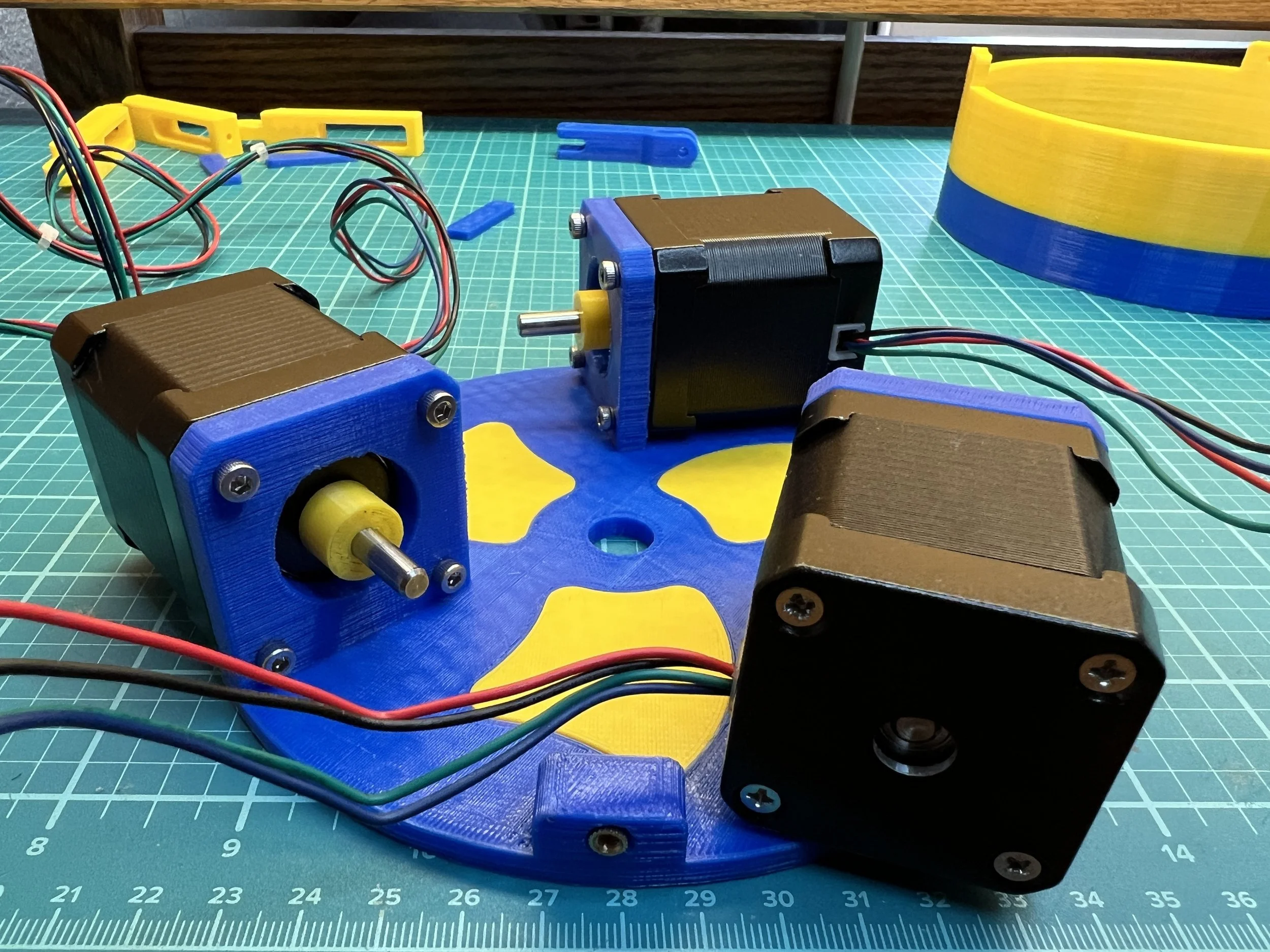
The robot is a 3RPS parallel manipulator. This is essentially a 3DOF platform with 3 legs each having a rotational joint and a spherical joint. Extending or contracting each leg will result in the platform being angled in a different way. This is done by each stepper motor. My biggest considerations when designing the balancer was to have sleekness and simplicity. For sleekness, I ensured that the electronics and most of the wires were well hidden. For simplicity, I decided to use 3 motors (3DOF) rather than the 6 motors (6DOF) used in version 1. Weighing the cost-benefits, I also chose not to use position encoders with the stepper motors. Using encoders would only eliminate the need to have the machine start at a common position. Without them, you simply just have to push the platform down every time.

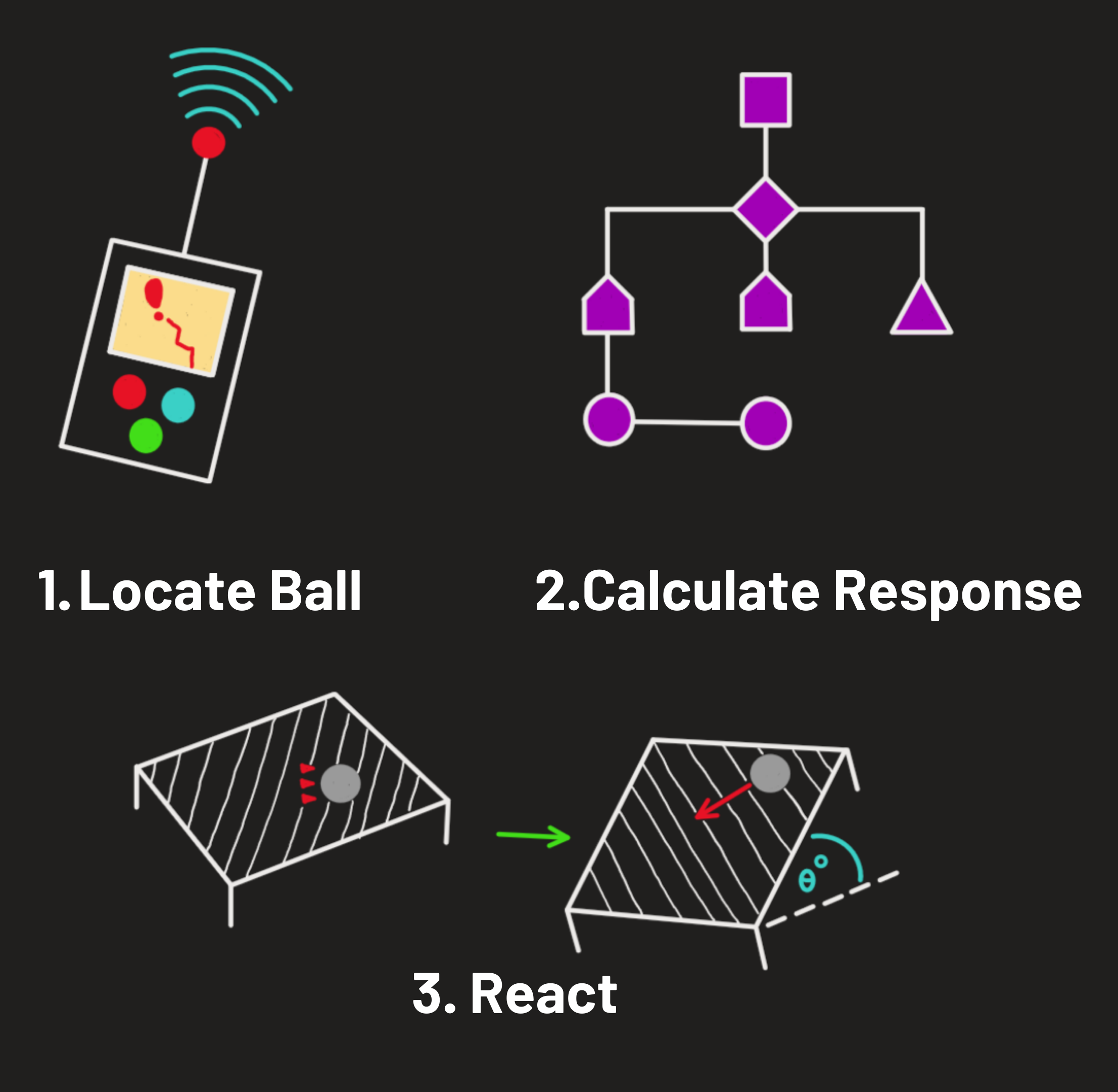
Ball Balancing PID Algorithm
The ball-balancing aspect of the code uses a PID algorithm. The algorithm constantly finds the most effective platform orientation to balance the ball.
Error - The error is defined as the distance from the ball to the setpoint. The setpoint in this case is the center of the platform.
Proportional Term (P) = kp*error --- The proportional term is proportional to the error
Integral Term (I) = ki*∫error --- The integral term is the accumulation of the error as time moves on. The integral term helps to fine-tune the position of the ball and ensure that the ball is exactly at the center.
Derivative Term (D) = kd*(d/dt)*error -- The derivative term is the derivative of the error which is essentially the speed of the ball. This term helps to slow the ball down.
Output = P + I + D ---The output value is the sum of the proportional, integral, and derivative terms. This output is essentially the most effective orientation to orient the platform in order to keep the ball from falling. The robot is constantly moving the ball toward the center (P), fine-tuning the position of the ball (I), and slowing the ball down (D). Each term in the output is tuned with its respective constants (kp, ki, kd) also known as the proportional gain, integral gain, and derivative gain. One thing that I found during testing is that the robot can balance the ball with a PD algorithm just as well as it can with a PID algorithm. The integral term just gets the ball exactly to the center of the platform if it's a little off.
The control algorithm consists of 2 PID algorithms for the X and Y directions of the error.
Synopsis of Events
The touchpad reads the position of the ball, waits 20 milliseconds, and reads the position of the ball again.
The program then calculates the terms in the PID algorithm. The output (aka the projected orientation of the platform) is fed to the inverse kinematic equations. These equations derive the position to move each stepper motor in order to achieve the platform's projected orientation.
With the new stepper motor positions, the speed and acceleration of the stepper motors are calculated and set. The stepper motors are then moved to their target positions which put the platform in the orientation that best slows the ball down and moves it to the center. The process is then repeated.